Raspberry Pi3(ラズベリーパイ3)とDHT11の温湿度センサーを使って室温を測定してみよう
こんばんは、ゆきです!
今日はちょっとご無沙汰していたRaspberry Piについて、DHT11を使用した温度センサーがちゃんと実現できたので、そのやり方等を説明したいと思います!
ちなみに基本的なやり方は下の記事を参考にしています。
簡単にRaspberryPi+DHT11で気温と湿度を通知するTweetBotを作る。
※上記の記事は配線に一部誤りがあるような気がする…。一応こちらでは図面通りの配線を目指したいと思いますです。こちらの方が誤りとのことであれば指摘頂けると幸いです。。(一応どちらでも動作しますが)
DHT11は以下のセンサーです。
DHT11をRaspberry Pi3とつなげてみよう
秋月電子さんのページにあるデータシートを見ると、以下のような回線図になっています。

むむ!!
( ^ω^)・・・よくわからないお
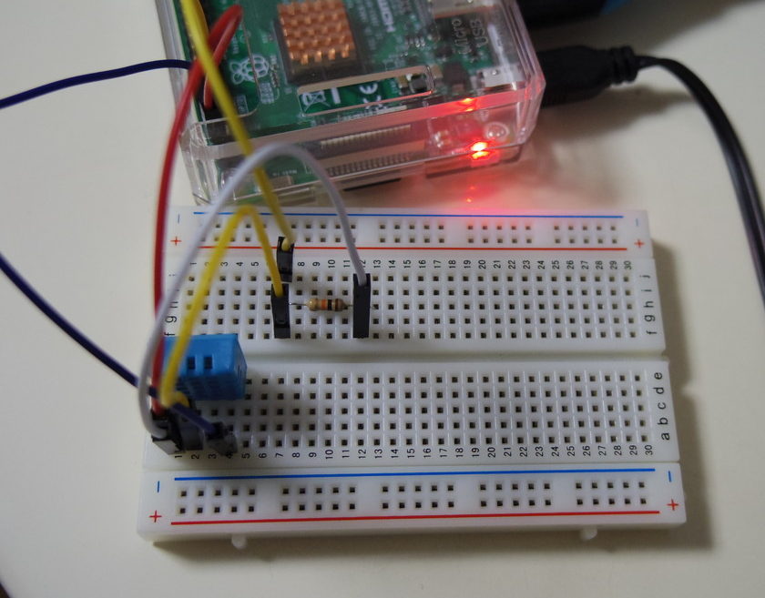
というわけで先ほどの記事や、文献等あれこれ調べた結果、以下のような配線にすると良い事が判りました。

リンク元の結線は以下のようになっており、抵抗の挿し方が異なります。プルアップ抵抗が必要なので、上記のような形が正しい配線ではないかと。
(もし間違っていたら指摘ください・・・。)
ちなみに、抵抗値は10kΩにしています。説明書では5.3kΩとなっていますが、多少はね?

記事中にセンサーエラーが多いとありますが、恐らくこの配線間違いにより電圧不安定な事があるのではないかと思います。
ちなみにGPIOは、Raspberry PI3のGPIOと記載のあるところならどこでもOKだ!ちなみにピン配置は下のような形になっています。

回路は下のような感じに組むと良いです。

ちゃんとできるまでに回路の配置を何回も間違えちまったぜ・・・
温湿度を測るプログラムはどう組めばよいか?
実はDHT11はセンサーとしての機能だけではなく、A/Dコンバーターも含まれており、通信までしてくれる凄い奴なのだ。ところが、この通信内容を読み取るには、Raspserry Pi側でその通信を読み込むためのプログラムを組む必要がある。
えっ、そんなの素人の私には無理ですぅ…
と思っていたんだけど、今の時代は凄い。できる人が用意してくれている。
なので有難くそれを使わせてもらおう。
まずはRaspberry Piのコマンドラインを開いて、以下のように打ち込みましょう。github(ソースコードを共有するサイト)からデータをダウンロードしたりするソフトです。
sudo apt-get install gitつづいて、任意のフォルダに移動して、以下のコマンドを打ちましょう。これで、DHT11を動作させるプログラムを入手することができます。
git clone https://github.com/szazo/DHT11_Python.git
ちなみにリナックスのコマンドについては、以下の本が大変勉強になります。

ファイルを開くと、以下のような構成だと思います。
ここで大事なのはdht11.pyとdht11_example.pyです。dht11.pyが信号を読み取り、温度と湿度に変換するプログラムで、dht11_example.pyはGPIOの初期化などを行い、コマンドラインで表示するためのプログラムになっています。

dht11.pyの中身は以下の通り。
import time
import RPi

class DHT11Result:
'DHT11 sensor result returned by DHT11.read() method'

ERR_NO_ERROR = 0
ERR_MISSING_DATA = 1
ERR_CRC = 2

error_code = ERR_NO_ERROR
temperature = -1
humidity = -1

def __init__(self, error_code, temperature, humidity):
self.error_code = error_code
self.temperature = temperature
self.humidity = humidity

def is_valid(self):
return self.error_code == DHT11Result.ERR_NO_ERROR

class DHT11:
'DHT11 sensor reader class for Raspberry'

__pin = 0

def __init__(self, pin):
self.__pin = pin

def read(self):
RPi.GPIO.setup(self.__pin, RPi.GPIO.OUT)

# send initial high
self.__send_and_sleep(RPi.GPIO.HIGH, 0.05)

# pull down to low
self.__send_and_sleep(RPi.GPIO.LOW, 0.02)

# change to input using pull up
RPi.GPIO.setup(self.__pin, RPi.GPIO.IN, RPi.GPIO.PUD_UP)

# collect data into an array
data = self.__collect_input()

# parse lengths of all data pull up periods
pull_up_lengths = self.__parse_data_pull_up_lengths(data)

# if bit count mismatch, return error (4 byte data + 1 byte checksum)
if len(pull_up_lengths) != 40:
return DHT11Result(DHT11Result.ERR_MISSING_DATA, 0, 0)

# calculate bits from lengths of the pull up periods
bits = self.__calculate_bits(pull_up_lengths)

# we have the bits, calculate bytes
the_bytes = self.__bits_to_bytes(bits)

# calculate checksum and check
checksum = self.__calculate_checksum(the_bytes)
if the_bytes[4] != checksum:
return DHT11Result(DHT11Result.ERR_CRC, 0, 0)

# ok, we have valid data, return it
return DHT11Result(DHT11Result.ERR_NO_ERROR, the_bytes[2], the_bytes[0])

def __send_and_sleep(self, output, sleep):
RPi.GPIO.output(self.__pin, output)
time.sleep(sleep)

def __collect_input(self):
# collect the data while unchanged found
unchanged_count = 0

# this is used to determine where is the end of the data
max_unchanged_count = 100

last = -1
data = []
while True:
current = RPi.GPIO.input(self.__pin)
data.append(current)
if last != current:
unchanged_count = 0
last = current
else:
unchanged_count += 1
if unchanged_count > max_unchanged_count:
break

return data

def __parse_data_pull_up_lengths(self, data):
STATE_INIT_PULL_DOWN = 1
STATE_INIT_PULL_UP = 2
STATE_DATA_FIRST_PULL_DOWN = 3
STATE_DATA_PULL_UP = 4
STATE_DATA_PULL_DOWN = 5

state = STATE_INIT_PULL_DOWN

lengths = [] # will contain the lengths of data pull up periods
current_length = 0 # will contain the length of the previous period

for i in range(len(data)):

current = data[i]
current_length += 1

if state == STATE_INIT_PULL_DOWN:
if current == RPi.GPIO.LOW:
# ok, we got the initial pull down
state = STATE_INIT_PULL_UP
continue
else:
continue
if state == STATE_INIT_PULL_UP:
if current == RPi.GPIO.HIGH:
# ok, we got the initial pull up
state = STATE_DATA_FIRST_PULL_DOWN
continue
else:
continue
if state == STATE_DATA_FIRST_PULL_DOWN:
if current == RPi.GPIO.LOW:
# we have the initial pull down, the next will be the data pull up
state = STATE_DATA_PULL_UP
continue
else:
continue
if state == STATE_DATA_PULL_UP:
if current == RPi.GPIO.HIGH:
# data pulled up, the length of this pull up will determine whether it is 0 or 1
current_length = 0
state = STATE_DATA_PULL_DOWN
continue
else:
continue
if state == STATE_DATA_PULL_DOWN:
if current == RPi.GPIO.LOW:
# pulled down, we store the length of the previous pull up period
lengths.append(current_length)
state = STATE_DATA_PULL_UP
continue
else:
continue

return lengths

def __calculate_bits(self, pull_up_lengths):
# find shortest and longest period
shortest_pull_up = 1000
longest_pull_up = 0

for i in range(0, len(pull_up_lengths)):
length = pull_up_lengths[i]
if length < shortest_pull_up: shortest_pull_up = length if length > longest_pull_up:
longest_pull_up = length

# use the halfway to determine whether the period it is long or short
halfway = shortest_pull_up + (longest_pull_up - shortest_pull_up) / 2
bits = []

for i in range(0, len(pull_up_lengths)):
bit = False
if pull_up_lengths[i] > halfway:
bit = True
bits.append(bit)

return bits

def __bits_to_bytes(self, bits):
the_bytes = []
byte = 0

for i in range(0, len(bits)):
byte = byte << 1
if (bits[i]):
byte = byte | 1
else:
byte = byte | 0
if ((i + 1) % 8 == 0):
the_bytes.append(byte)
byte = 0

return the_bytes

def __calculate_checksum(self, the_bytes):
return the_bytes[0] + the_bytes[1] + the_bytes[2] + the_bytes[3] & 255
続いてdht11_example.pyは以下の通り。
import RPi.GPIO as GPIO
import dht11
import time
import datetime

# initialize GPIO
GPIO.setwarnings(False)
GPIO.setmode(GPIO.BCM)
GPIO.cleanup()

# read data using pin 14
instance = dht11.DHT11(pin=14)

while True:
    result = instance.read()
    if result.is_valid():
        print("Last valid input: " + str(datetime.datetime.now()))
        print("Temperature: %d C" % result.temperature)
        print("Humidity: %d %%" % result.humidity)

    time.sleep(1)
12行目のpin=14と記載のある箇所は、もしGPIOピンの接続箇所を変更しているのであれば、そのGPIOの番号に変更する必要があります。
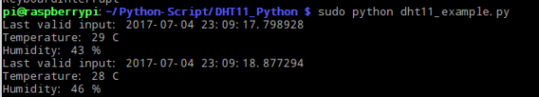
最後に、プログラムの入っているフォルダに移動して、コマンドラインから以下のコマンドを入力します。
sudo python dht11_example.py
下の画像のように温度と湿度の値が表示されれば完成です。
次はSQLiteでデータ蓄積するのだ。
配線失敗談
実は初めてのRapsberry Pi3、初めての電子工作という事もあり、最初は全く動きませんでした。原因は配線ミス。テスターも持たずやっていたので、繋ぐ場所を間違えていることに気づかなかったり、ハマってました…
失敗その1
抵抗値の値が10kΩ×5と300Ωを直列につないでいる。1kΩと読み間違えちゃった(テヘッ
実はこれはあまり大した間違いではなかったという( ^ω^)・・・

失敗その2
NCにケーブルを指している。そら動かんわ!

以上!
